

 Buy Now
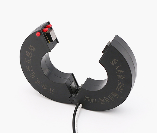
Input current: 0~2000A; Output current: 0~100mA; Output voltage: 0~1V
General measurement and protection in power systems with high mobility, cramped space or uninterruptible power systems.
Passed ISO 9001:2015; fully compliant with RoHS and REACH requirements


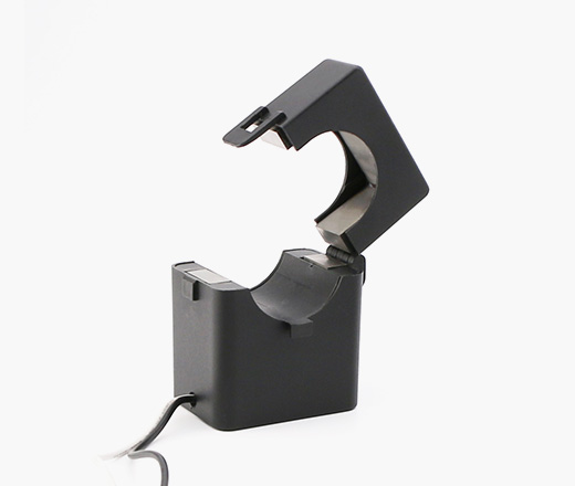
Split core design, low core loss, high precision
No need to disconnect the busbar, easy installation, no impact on customers' normal electricity use
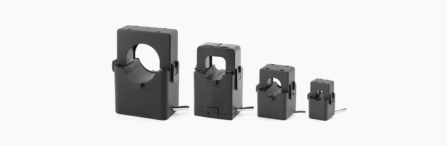
Beautiful appearance, small size, light weight
Snap-on opening and closing structure, easy opening and closing

Equipment maximum voltage 0.66kV
Rated input 0~2000A
Rated output 5A/1A/mA/mV
Operating frequency 50Hz~60HZ
Power frequency withstand voltage 4000V/1mA/1min (50Hz)
Insulation resistance DC500V/1000M2/min

Operating environment: temperature -40℃~ +85℃
Storage environment: temperature -40℃~ +85℃
Relative humidity: no more than 95% (25℃)
Reference standard: IEC 60044-1&GB&T 20840.1-2017&ANSI C57.13
ELECTRICAL PROPERTIES(at 25°C) Rated Output Current mA/Voltage mV | ||||||
Model | Input Current | Maximum current | Output Current | Output voltage | Load resistance | Accuracy |
KCT-FK06 | 0-25A | 30A | 0-100mA | 0-1V | 0-10Ω | 1.0 |
KCT-FK10 | 0-63A | 63A | 0-100mA | 0-1V | 0-10Ω | 1.0 |
KCT-FK16 | 0-120A | 150A | 0-100mA | 0-1V | 0-10Ω | 0.5/1.0 |
KCT-FK20 | 0-200A | 240A | 0-100mA | 0-1V | 0-10Ω | 0.5/1.0 |
KCT-FK24 | 0-300A | 360A | 0-100mA | 0-1V | 0-10Ω | 0.5S/0.5 |
KCT-FK36 | 0-600A | 720A | 0-100mA | 0-1V | 0-10Ω | 0.5S/0.5 |
KCT-FK50 | 0-1000A | 1200A | 0-100mA | 0-1V | 0-10Ω | 0.2/0.5S |
KCT-FK50B | 0-1000A | 1200A | 0-100mA | 0-1V | 0-10Ω | 0.2/0.5S |
KCT-FK64 | 0-2000A | 2000A | 0-100mA | 0-1V | 0-10Ω | 0.2/0.5S |
ELECTRICAL PROPERTIES(at 25°C) Rated Output Current 5A/1A | |||||
Model | Input Current(A) | load(VA) | |||
0.2 | 0.5S | 0.5 | 1.0 | ||
KCT-FK24 | 100 | / | / | / | / |
200 | / | / | / | 1 | |
300 | / | / | 1 | 2.5 | |
KCT-FK36 | 300 | / | / | 1 | 2.5 |
400 | / | 1 | 2.5 | 5 | |
500 | / | 2.5 | 5 | 7.5 | |
600 | / | 2.5 | 5 | 7.5 | |
KCT-FK50 | 600 | 2.5 | 5 | 7.5 | 10 |
800 | 5 | 7.5 | 10 | 15 | |
1000 | 5 | 10 | 15 | 20 | |
KCT-FK50B | 600 | 2.5 | 3.75 | 5 | 7.5 |
800 | 3.75 | 5 | 7.5 | 10 | |
1000 | 5 | 7.5 | 10 | 20 | |
| KCT-FK64 | 1000 | 5 | 10 | 15 | 20 |
1500 | 10 | 15 | 20 | 25 | |
2000 | 15 | 20 | 25 | 30 | |

Dimensional tolerance: ±1.0mm(Unless otherwise specified) Lead Tolerance:±5mm
Model | A(mm) | B(mm) | C(mm) | D(mm) | E(mm) | F(mm) |
KCT-FK06 | 6 | 25 | 16 | 18 | 11 | 11 |
KCT-FK10 | 10 | 40 | 23 | 26 | 14 | 16 |
KCT-FK16 | 16 | 46 | 29.5 | 32 | 19.5 | 19 |
KCT-FK20 | 20 | 56 | 36 | 36 | 25.5 | 24 |
KCT-FK24 | 24 | 68 | 45 | 36 | 22 | 29 |
KCT-FK36 | 36 | 85 | 57 | 42 | 24 | 37 |
KCT-FK50 | 50 | 108 | 78 | 48 | 27 | 48 |
KCT-FK50B | 50 | 103 | 73 | 60 | 27 | 46 |
KCT-FK64 | 64 | 134 | 95 | 60 | 29 | 58 |

Vout=Is x RL RL≤10 Ohm
Note: This schematic diagram is the basic working principle of the transformer. The transformer sampling circuit can be designed for customers.

We are a service provider that can provide a complete set of electronic component technology. Specializing in the production, research and development, and sales services of amorphous nanocrystalline iron cores, transformers, and sensors.


If you have any questions or need assistance, please feel free to contact our team at any time.
3rd Floor, Building 4A, Huiye Technology Park, Fenghuang Street, Guangming District, Shenzhen

 EN
EN
 CN
CN