

 Buy Now
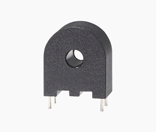
Input current: 2mA; Output current: 2mA; Current ratio: 1000:1000
Applicable to convert high voltage signals into proportional low current signals, facilitating the use of measurement and protection equipment.
Passed ISO 9001:2015; fully compliant with RoHS and REACH requirements


Adopt nanocrystalline magnetic core (high precision, good linearity)
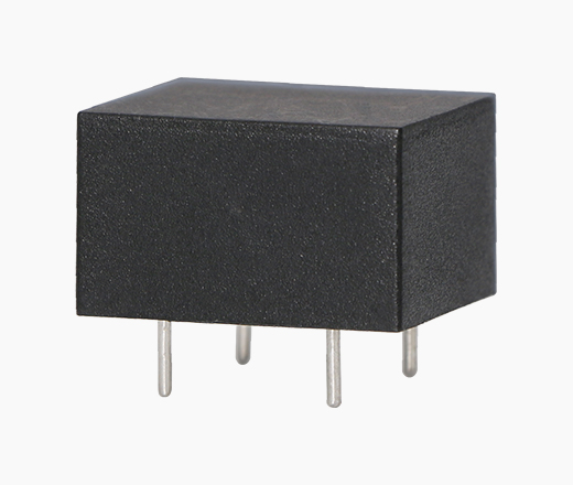
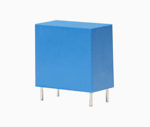
Epoxy potting, safe and reliable;
Flame retardant (compliant with UL94-V0);
Environmental protection (compliant with EU RoHS and REACH standards)
Small size, light weight, easy to assemble and weld.

Detecting overload current
Ground fault detection
Metering
Analog to digital circuits

Operating environment: temperature -40℃~ +85℃,
Storage environment: temperature -40℃~ +85℃,
Relative humidity: no more than 95% (25℃)
Reference standard: IEC 60044-1&GB&T 20840.1-2017&ANSI C57.13
ELECTRICAL PROPERTIES(at 25°C) | |||||||||
Model | Input Current | Output Current | Turns Ratio | Linear range | Phase Difference | Accuracy | Load resistance | Pressure resistance | Operating frequency |
SPT101 | 2mA | 2mA | 1000:1000 | 5~120% | ≤30’ | 0.2 | ≤20Ω | 3000V | 50Hz~60Hz |
Precautions∶1、Pay attention to the load connected to the secondary of the transformer.,Exceeding the rated load capacity may result in reduced accuracy or saturation.。
2. If there is no suitable product for your use in the above table, our company can tailor-make products for you according to your technical and structural requirements.
Dimension units: (mm)
Dimensional tolerance: ±0.5mm(unless otherwise specified), pitch tolerance:±0.3mm
Note:Unless required, terminal resistors and one turn primary are not provided
.png")
Note: This schematic diagram is the basic working principle of the transformer, and the transformer sampling circuit can be customized.


We are a service provider that can provide a complete set of electronic component technology. Specializing in the production, research and development, and sales services of amorphous nanocrystalline iron cores, transformers, and sensors.


If you have any questions or need assistance, please feel free to contact our team at any time.
3rd Floor, Building 4A, Huiye Technology Park, Fenghuang Street, Guangming District, Shenzhen

 EN
EN
 CN
CN